17,005 Documents in our Technical Library
2727852 Total Downloads

Newest Additions

NASA-RP-1060 Subsonic Aircraft: Evolution and the Matching of Size to Performance
AA-CP-20212-001
AA-CP-20212-001
ADPO10769 Occurrence of Corrosion in Airframes
The purpose of this lecture is to provide an overview ...
MIL-STD-1759 Rivets and Rivet Type Fasteners Preferred for Design
The purpose of this book form standard is to provide ...
MIL-STD-810G Environmental Engineering Considerations and Laboratory Tests
This standard contains materiel acquisition program planning and engineering direction ...

naca-tn-1752

  • Version
  • 108 Downloads
  • 698.15 KB File Size
  • 1 File Count
  • December 6, 2016 Create Date
  • December 6, 2016 Last Updated
Scroll for Details

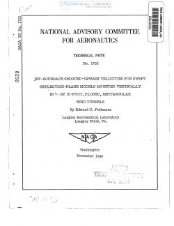
National Advisory Committee for Aeronautics, Technical Notes - Jet Boundary Induced Upwash Velocities for Swept Reflection Plane Models Mounted Vertically in 7x10', Closed, Rectangular Wind Tunnels
naca-tn-1752-jet-boundary-induced-upwash-velocities-for-swept-reflection-plane-models-mounted-vertically-in-7x10-closed-1

Numerical values of the calculated boundary-induced-upwash
velocities necessary for the determination of the Jet-boundary
corrections for swept reflection-plane models mounted vertically in
7- by 10-foot, closed, rectangular wind tunnels are presented in
chart form. A few calculations made by using these values of upwash,
indicatedathat for plan forms having taper ratios of about 1/2,
sweep haa.essentially no effect on the correction- Except for
extreme cases of inverse taper the effect of sweep appears to be less
than 10 percent for sweep angles up to 60°.

The general methods of calculating the various corrections
necessitated by the influence of the Jet boundaries upon the
characteristics of semispan models mounted on reflection planes in
rectangular wind tunnels have been developed in reference 1. Also
presented in reference 1 are numerical values of the corrections for
unBWept wings mounted from the 7-foot wall in 7- by 10- foot, closed,
rectangular wind tunnels.

The purpose of the present paper is, to present values of the
Jet-boundary—induced-upwash velocities from which the corrections
for swept wings mounted from the 10-foot wall in 7- by 10-foot,
closed, rectangular wind tunnels can be calculated by the methods of
reference 1.

A complete discussion of the image method of satisfying the
boundary condition and calculating the induced upwash velocity for
closed rectangular tunnels is presented in reference 1. The boundary-
induced-upwash velocity at the lifting line of an unswept wing may be
determined from a. two-dimensional image arrangement satisfying the
bomdazry conditions for a. single trailing vortex and its reflection.
Values of this bomdary-induced-upwash velocity for trailing vortices
located at various distances s from the reflection wall are presented
in figure 1.

The upwash velocity at the lifting line for swept wings may be
determined by the use of horseshoe-type vortices with swept bound
vortices.

FileAction
naca-tn-1752 Jet Boundary Induced Upwash Velocities for Swept Reflection Plane Models Mounted Vertically in 7x10', Closed, Rectangular Wind Tunnels.pdfDownload 

Comment On This Post

Your email address will not be published. Required fields are marked *

naca-tn-1752

  • Version
  • 108 Downloads
  • 698.15 KB File Size
  • 1 File Count
  • December 6, 2016 Create Date
  • December 6, 2016 Last Updated
Scroll for Details

National Advisory Committee for Aeronautics, Technical Notes - Jet Boundary Induced Upwash Velocities for Swept Reflection Plane Models Mounted Vertically in 7x10', Closed, Rectangular Wind Tunnels

naca-tn-1752-jet-boundary-induced-upwash-velocities-for-swept-reflection-plane-models-mounted-vertically-in-7x10-closed-1

Numerical values of the calculated boundary-induced-upwash
velocities necessary for the determination of the Jet-boundary
corrections for swept reflection-plane models mounted vertically in
7- by 10-foot, closed, rectangular wind tunnels are presented in
chart form. A few calculations made by using these values of upwash,
indicatedathat for plan forms having taper ratios of about 1/2,
sweep haa.essentially no effect on the correction- Except for
extreme cases of inverse taper the effect of sweep appears to be less
than 10 percent for sweep angles up to 60°.

The general methods of calculating the various corrections
necessitated by the influence of the Jet boundaries upon the
characteristics of semispan models mounted on reflection planes in
rectangular wind tunnels have been developed in reference 1. Also
presented in reference 1 are numerical values of the corrections for
unBWept wings mounted from the 7-foot wall in 7- by 10- foot, closed,
rectangular wind tunnels.

The purpose of the present paper is, to present values of the
Jet-boundary—induced-upwash velocities from which the corrections
for swept wings mounted from the 10-foot wall in 7- by 10-foot,
closed, rectangular wind tunnels can be calculated by the methods of
reference 1.

A complete discussion of the image method of satisfying the
boundary condition and calculating the induced upwash velocity for
closed rectangular tunnels is presented in reference 1. The boundary-
induced-upwash velocity at the lifting line of an unswept wing may be
determined from a. two-dimensional image arrangement satisfying the
bomdazry conditions for a. single trailing vortex and its reflection.
Values of this bomdary-induced-upwash velocity for trailing vortices
located at various distances s from the reflection wall are presented
in figure 1.

The upwash velocity at the lifting line for swept wings may be
determined by the use of horseshoe-type vortices with swept bound
vortices.

FileAction
naca-tn-1752 Jet Boundary Induced Upwash Velocities for Swept Reflection Plane Models Mounted Vertically in 7x10', Closed, Rectangular Wind Tunnels.pdfDownload 
17,005 Documents in our Technical Library
2727852 Total Downloads

Search The Technical Library

Newest Additions

NASA-RP-1060 Subsonic Aircraft: Evolution and the Matching of Size to Performance
AA-CP-20212-001
AA-CP-20212-001
ADPO10769 Occurrence of Corrosion in Airframes
The purpose of this lecture is to provide an overview ...
MIL-STD-1759 Rivets and Rivet Type Fasteners Preferred for Design
The purpose of this book form standard is to provide ...
MIL-STD-810G Environmental Engineering Considerations and Laboratory Tests
This standard contains materiel acquisition program planning and engineering direction ...