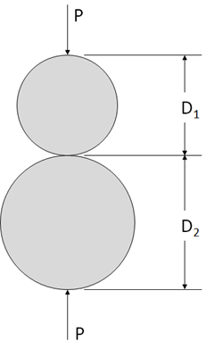
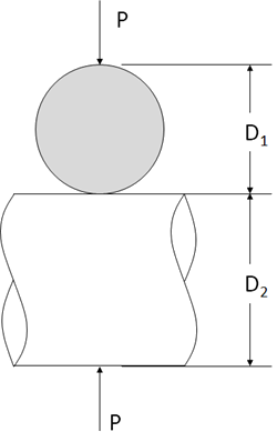
12.3.1.1. Sphere on Sphere
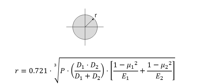
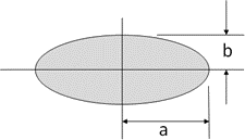
Shape of Contact Area:
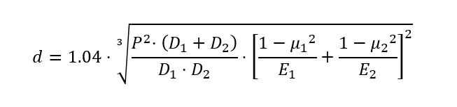
Deflection:
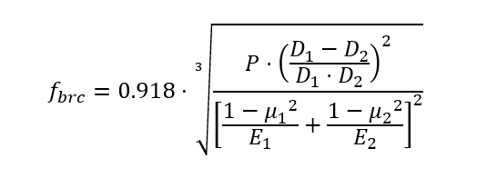
Maximum Bearing Compression Stress:
A spreadsheet for this method is available at the link below:
12.3.1.2. Sphere in Spherical Socket
Shape of Contact Area:
Deflection:
Maximum Bearing Compression Stress:
A spreadsheet for this method is available at the link below:
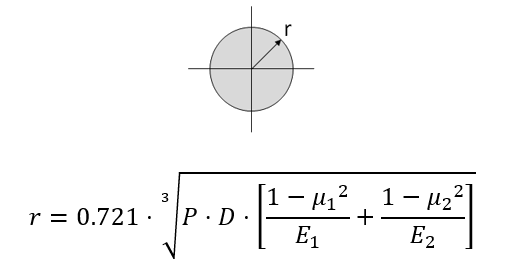
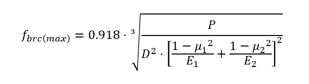
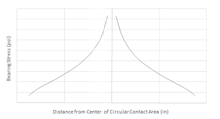
12.3.1.3. Sphere on a Flat Panel
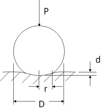
Shape of Contact Area:
Maximum Bearing Compression Stress:
Distribution of normal pressure in the contact area as a function of distance (r’) from the center of the circle:
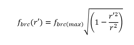
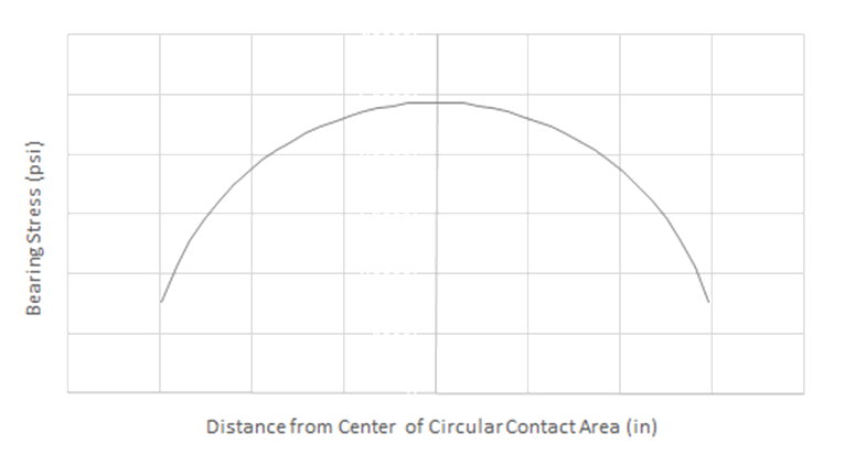
Figure 12.3.1‑4: Sphere on Flat Panel Contact – Bearing Stress Distribution
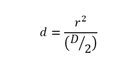
Depth of Indentation:
A spreadsheet for this method is available at the link below:
12.3.1.4. Cylinder on a Cylinder with Axes Parallel
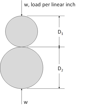
Shape of Contact Area:
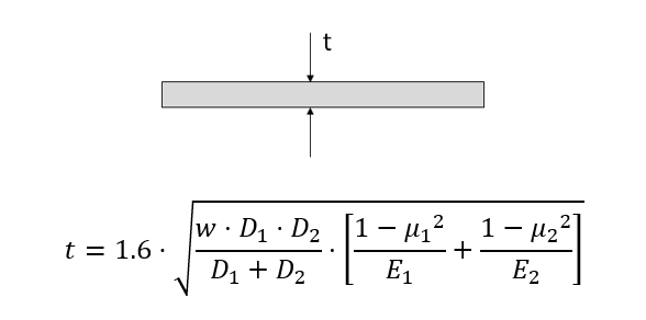
Maximum Bearing Compression Stress:
A spreadsheet for this method is available at the link below:
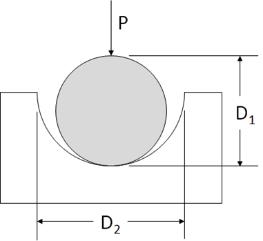
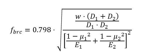
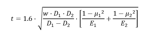
12.3.1.5. Cylinder in a Cylindrical Groove
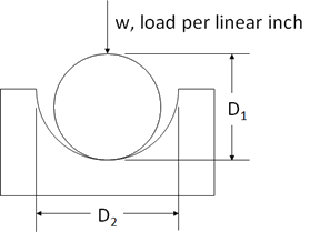
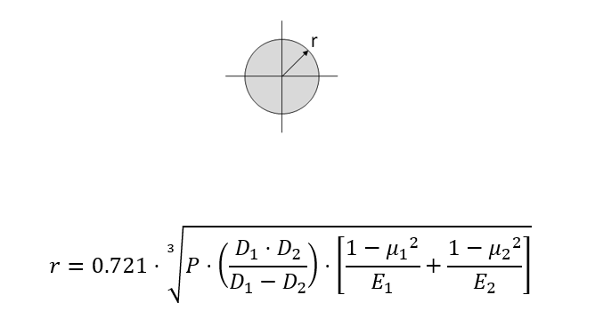
Shape of Contact Area:

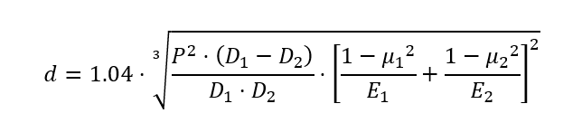
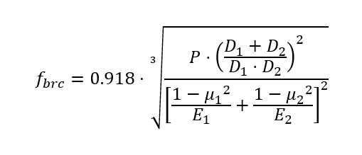
Maximum Bearing Compression Stress:
A spreadsheet for this method is available at the link below:
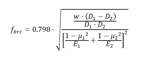
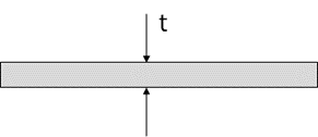
12.3.1.6. Cylinder on a Flat Panel
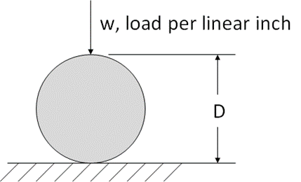
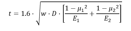
Shape of Contact Area:
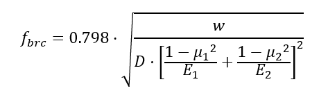
Maximum Bearing Compression Stress:
A spreadsheet for this method is available at the link below:
12.3.1.7. Cylinder on a Cylinder with Axes Perpendicular
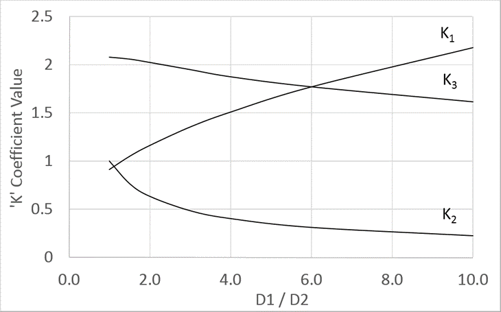
Shape of Contact Area:
The contact area between the two cylinders is derived using the following 3 parameters: K1, K2 and K3.
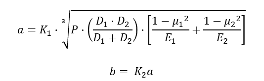
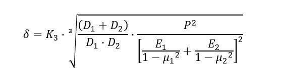
Deflection:
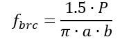
Maximum Bearing Compression Stress:
A spreadsheet for this method is available at the link below:
12.3.1.8. Rigid Knife Edge on a Panel
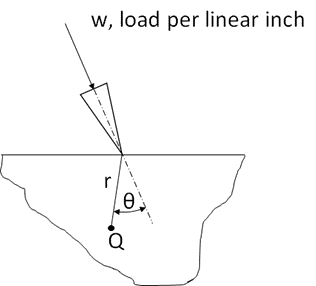
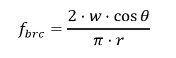
Maximum Bearing Compression Stress, at any point Q:
A spreadsheet for this method is available at the link below:
12.3.1.9. Rigid Cone on a Panel
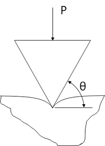
Maximum Deflection:
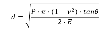
Depth of the Contact Region:
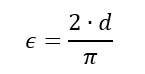
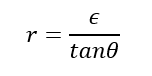
Radius of the Contact Region:
Distribution of normal pressure in the contact area as a function of distance (r’) from the center of the circle:
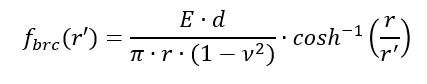
The pressure distribution has a singularity at the center of the contact region.
A spreadsheet for this method is available at the link below: