12.5.2.1. General Strength of Fusion Welded Joint of Steel Alloys
Allowable fusion weld-metal strengths of steel alloys are shown below. Design allowable stresses for the weld metal are based on 85% of the respective minimum tensile ultimate value.

 MIL-HNDBK-5H, 1998)
 Strength of steel in the heat affected zone:

 MIL-HNDBK-5H, 1998)
 (![]() NASA TM X-73305, 1975) Table B 1.2.3.1 gives the following general allowable strengths for welded steel joints. Additional data for specific steel alloys is shown in the following sections:
NASA TM X-73305, 1975) Table B 1.2.3.1 gives the following general allowable strengths for welded steel joints. Additional data for specific steel alloys is shown in the following sections:
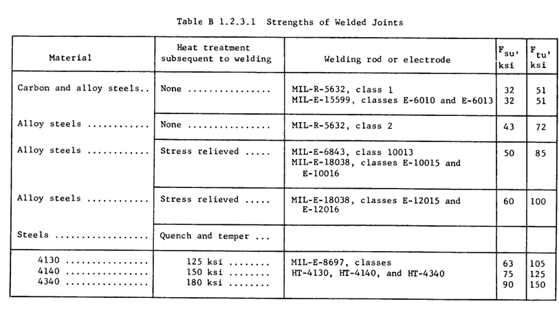
 NASA TM X-73305, 1975)
 12.5.2.2. Strength of Welded 4130 Steel
The most common steel used for welded applications in aircraft, and in general strength-critical applications outside of the aircraft industry is 4130 alloy Steel. There is surprisingly little useful data on the strength of welded 4130 in the public domain. This NACA paper (![]() NACA-TN-1261, 1947) has some useful information. The values in this reference are not statistical basis allowable values. It is recommended that a minimum margin of safety of 15% be maintained when using the values from these tables.
NACA-TN-1261, 1947) has some useful information. The values in this reference are not statistical basis allowable values. It is recommended that a minimum margin of safety of 15% be maintained when using the values from these tables.

 NACA-TN-1261, 1947)
 The ratio of Ftu to Fty and to Fsu can be assumed to be the same as for the weld as it is for the original stock 4130 alloy.
12.5.2.3. Strength of Welded 17-4 Steel
The following tables are taken from (![]() OTS-PB-151074 DMIC Report 118, 1959). Some care should be taken in using these values as they are not statistical basis allowable values. It is recommended that a minimum margin of safety of 15% be maintained when using the values from these tables.
OTS-PB-151074 DMIC Report 118, 1959). Some care should be taken in using these values as they are not statistical basis allowable values. It is recommended that a minimum margin of safety of 15% be maintained when using the values from these tables.
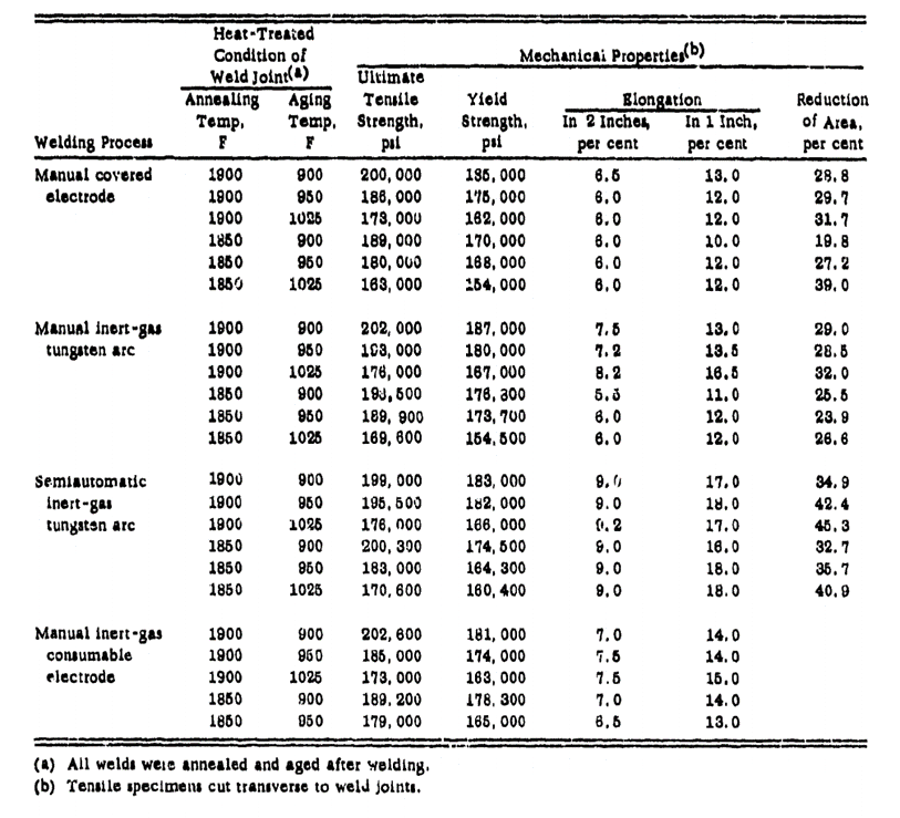
 OTS-PB-151074 DMIC Report 118, 1959)
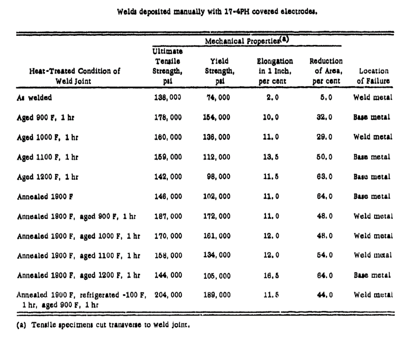
 OTS-PB-151074 DMIC Report 118, 1959)
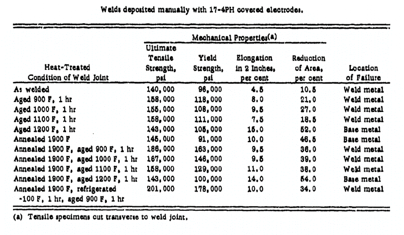
 OTS-PB-151074 DMIC Report 118, 1959)
 Note that the as-welded data in the table above has a low elongation at failure (4.5%) which indicates brittleness and a propensity to crack. It is recommended that at least the minimal 1 hour of aging at 900F is done for all welded joints in 17-4 stainless steel. This increases the strength and durability of the weld.
Effect of temperature on the strength of 17-4PH weld:
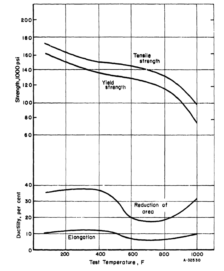
 OTS-PB-151074 DMIC Report 118, 1959)
 12.5.2.4. Strength of Welded 17-7 Steel
The following tables are taken from (![]() OTS-PB-151074 DMIC Report 118, 1959). As previously, some care should be taken in using these values as they are not statistical basis allowable values. It is recommended that a minimum margin of safety of 15% be maintained when using the values from these tables.
OTS-PB-151074 DMIC Report 118, 1959). As previously, some care should be taken in using these values as they are not statistical basis allowable values. It is recommended that a minimum margin of safety of 15% be maintained when using the values from these tables.
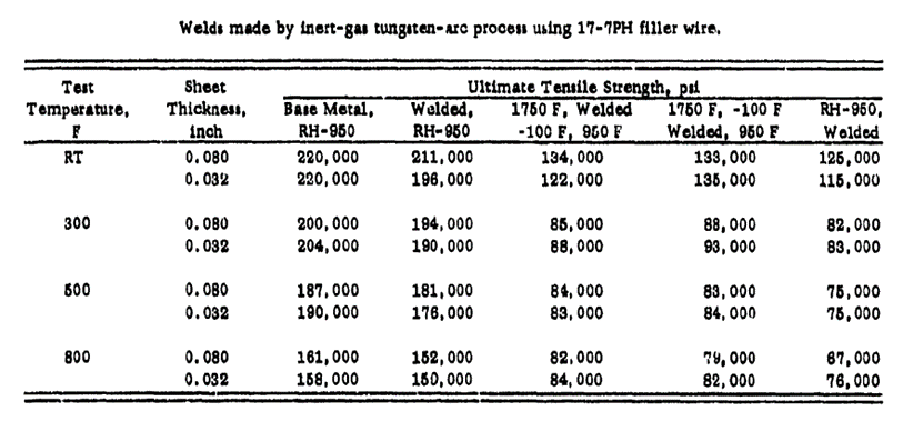
 OTS-PB-151074 DMIC Report 118, 1959)
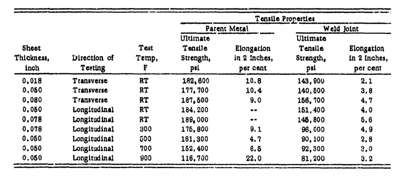
 OTS-PB-151074 DMIC Report 118, 1959)
 12.5.2.5. Strength of Welded 15-7 Steel
The following tables are taken from (![]() OTS-PB-151074 DMIC Report 118, 1959). As previously, it is recommended that a minimum margin of safety of 15% be maintained when using the values from these tables.
OTS-PB-151074 DMIC Report 118, 1959). As previously, it is recommended that a minimum margin of safety of 15% be maintained when using the values from these tables.
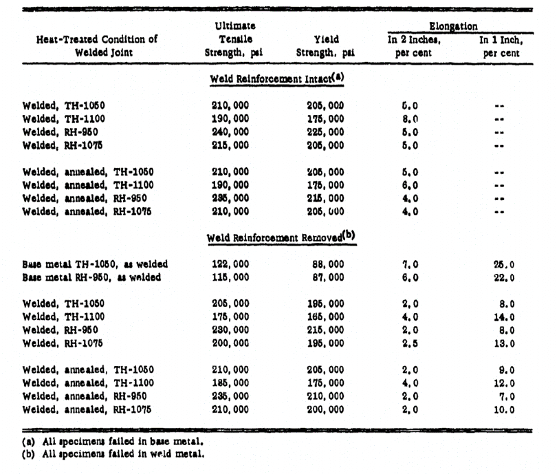
 OTS-PB-151074 DMIC Report 118, 1959)