naca-wr-l-449

  • Version
  • 146 Downloads
  • 1.47 MB File Size
  • 1 File Count
  • April 3, 2017 Create Date
  • April 3, 2017 Last Updated
Scroll for Details

Wind Tunnel Investigation of an NACA 23021 Airfoil with Two Sized of Balanced Split Flaps
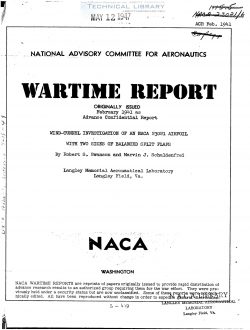
An investigation has been made in the HAGA 7- by 10-
foot wind tunnel of a larqe—chord nice 23021 airfoil with
a l5—percent~chord and a 25—percent-cherd balanced split
flap of Clark Y profile. to determine the aerodynamic sec-
tion characteristics of the airfoil-flap combinations as
affected by the size. nose location, and deflection of the
flaps. Section lift, draq, and pitching—moment character—
istics are presented in the form of contours of flap nose
location for given values of the lift, drag. and pitching—
moment coefficients and complete aerodynamic section char-
acteristics are presented for four representative loca-
tions of each flap. The two balanced split flaps are com-
pared with a slotted—flap arrangement developed in a pre-
vious invostifiation.

The optimum aerodynamic arranzement of either bal-
anced split flap. from considerations of minimum profile-
drag coefficients for take—off and climb. was an arrangement
comparable to the Fowler flap. The 15-percent balanced
split flap was better over the moderate lift ranze, while
the 25—parcent balanced split flap was better over the
high—lift range. Both balanced split flaps were better
than the best slotted flap of a previous investiqation.
except in the hixh-lift range. where the slotted flap den
veloped a higher maximum lift coefficient than did the 15-
percent balanced split flap.

From considerations of maximum lift coefficient. the
Fowler arranaement of the 25—percent_balanced split flap
was the optimum. giving an increment of maximum lift coef-
ficient of about 1.82. The best slotted flap of a previ-
ous investigation save an increment of 1.47. while the
Fowler arrangement of the 15-porcent balanced split flap
fiave an increment of 1.24. The optimum position for the
lE—pereent balanced split flap was a high drag position
at 5 percent ahead of the trailing edge and 3 percent below
the chord line. where the increment of maximum lift coef-
ficiont'ebtained was 1.31.
In seneral. under comparable conditions. the previ—
ouslr developed slotted flap had equal or senewhat lower
pitching-moment coefficients than either size of balanced
split flap.

INTRODUCTIOE

The National Advisory Committee for Aeronautics has
undertaken an extensive investigation of various airfoil—
flap combinations to furnish information applicable to the
aerodynamic and structural design of hifih—lift devices
with the view toward increasing the safety and perform—
ance of airplanes. A high—lift device capable of produc-
inz high lift with low drag for take—off and initial climb.
and hish lift with variable drag for landing is believed
desirable. Other important features are: no increase in
dra: with flaps neutral} small change in pitching moment
with flap deflection. low operating forces. freedom from
possible icing. and structural simplicity.

Some promising airfoil—flap combinations have been
developed for the NAGA 23012 and 23021 airfoils. Aerody-
namic data for the HACA 23021 airfoil equipped with single
slotted flaps are :iven in references 1 and 2, with split
flaps in reference 3. with plain and slotted extensible
flaps in reference 4. and with double slotted flaps in
reference 5. Structural data on this airfoil equipped
with a single slotted flap and with a split flap are given
in reference 6.

The type of flap most commonly used on modern air-
plants is some form of split flap. In order to furnish
information on this type of flap, an investigation has _
been made of an NASA 23012 airfoil equipped with two sizes
of balanced split flaps. and is reported in reference 7.
The investisation of balanced split flaps has been extend—
ed to the thicker NACA 23021 airfoil and the results are
presented herein. 3? a balanced split flap is meant a
split flap of airfoil section which is displaced rearward
as well as deflected downward.

FileAction
naca-wr-l-449 Wind Tunnel Investigation of an NACA 23021 Airfoil with Two Sized of Balanced Split Flaps.pdfDownload 

Comment On This Post

Your email address will not be published. Required fields are marked *

naca-wr-l-449

  • Version
  • 146 Downloads
  • 1.47 MB File Size
  • 1 File Count
  • April 3, 2017 Create Date
  • April 3, 2017 Last Updated
Scroll for Details

Wind Tunnel Investigation of an NACA 23021 Airfoil with Two Sized of Balanced Split Flaps

An investigation has been made in the HAGA 7- by 10-
foot wind tunnel of a larqe—chord nice 23021 airfoil with
a l5—percent~chord and a 25—percent-cherd balanced split
flap of Clark Y profile. to determine the aerodynamic sec-
tion characteristics of the airfoil-flap combinations as
affected by the size. nose location, and deflection of the
flaps. Section lift, draq, and pitching—moment character—
istics are presented in the form of contours of flap nose
location for given values of the lift, drag. and pitching—
moment coefficients and complete aerodynamic section char-
acteristics are presented for four representative loca-
tions of each flap. The two balanced split flaps are com-
pared with a slotted—flap arrangement developed in a pre-
vious invostifiation.

The optimum aerodynamic arranzement of either bal-
anced split flap. from considerations of minimum profile-
drag coefficients for take—off and climb. was an arrangement
comparable to the Fowler flap. The 15-percent balanced
split flap was better over the moderate lift ranze, while
the 25—parcent balanced split flap was better over the
high—lift range. Both balanced split flaps were better
than the best slotted flap of a previous investiqation.
except in the hixh-lift range. where the slotted flap den
veloped a higher maximum lift coefficient than did the 15-
percent balanced split flap.

From considerations of maximum lift coefficient. the
Fowler arranaement of the 25—percent_balanced split flap
was the optimum. giving an increment of maximum lift coef-
ficient of about 1.82. The best slotted flap of a previ-
ous investigation save an increment of 1.47. while the
Fowler arrangement of the 15-porcent balanced split flap
fiave an increment of 1.24. The optimum position for the
lE—pereent balanced split flap was a high drag position
at 5 percent ahead of the trailing edge and 3 percent below
the chord line. where the increment of maximum lift coef-
ficiont'ebtained was 1.31.
In seneral. under comparable conditions. the previ—
ouslr developed slotted flap had equal or senewhat lower
pitching-moment coefficients than either size of balanced
split flap.

INTRODUCTIOE

The National Advisory Committee for Aeronautics has
undertaken an extensive investigation of various airfoil—
flap combinations to furnish information applicable to the
aerodynamic and structural design of hifih—lift devices
with the view toward increasing the safety and perform—
ance of airplanes. A high—lift device capable of produc-
inz high lift with low drag for take—off and initial climb.
and hish lift with variable drag for landing is believed
desirable. Other important features are: no increase in
dra: with flaps neutral} small change in pitching moment
with flap deflection. low operating forces. freedom from
possible icing. and structural simplicity.

Some promising airfoil—flap combinations have been
developed for the NAGA 23012 and 23021 airfoils. Aerody-
namic data for the HACA 23021 airfoil equipped with single
slotted flaps are :iven in references 1 and 2, with split
flaps in reference 3. with plain and slotted extensible
flaps in reference 4. and with double slotted flaps in
reference 5. Structural data on this airfoil equipped
with a single slotted flap and with a split flap are given
in reference 6.

The type of flap most commonly used on modern air-
plants is some form of split flap. In order to furnish
information on this type of flap, an investigation has _
been made of an NASA 23012 airfoil equipped with two sizes
of balanced split flaps. and is reported in reference 7.
The investisation of balanced split flaps has been extend—
ed to the thicker NACA 23021 airfoil and the results are
presented herein. 3? a balanced split flap is meant a
split flap of airfoil section which is displaced rearward
as well as deflected downward.

FileAction
naca-wr-l-449 Wind Tunnel Investigation of an NACA 23021 Airfoil with Two Sized of Balanced Split Flaps.pdfDownload 
17,005 Documents in our Technical Library
2729760 Total Downloads

Search The Technical Library

Newest Additions

NASA-RP-1060 Subsonic Aircraft: Evolution and the Matching of Size to Performance
AA-CP-20212-001
AA-CP-20212-001
ADPO10769 Occurrence of Corrosion in Airframes
The purpose of this lecture is to provide an overview ...
MIL-STD-1759 Rivets and Rivet Type Fasteners Preferred for Design
The purpose of this book form standard is to provide ...
MIL-STD-810G Environmental Engineering Considerations and Laboratory Tests
This standard contains materiel acquisition program planning and engineering direction ...