To refine the simple buckling analysis in the first post you can take account of the panel edge fixity and account for material non linearity. This post concerns how to take account of panel edge fixity.
The method I prefer is defined in (NACA-TN-2661, 1952), this reference is the grand daddy of aircraft buckling source material. This paper along with it’s partner (NACA-TN-2662, 1952) are indispensable reading for any engineer working on developing lightweight metal structures.
Section 3.6 of (NACA-TN-2661, 1952) gives a method for modifying the simply supported panel shear buckling coefficient k to account for the stiffness of the panel edge members. This method gives a factor between 1.0 (simply supported) and 1.62 (clamped). It is true that there does exist a approximate consistent factor between simply supported and clamped shear buckling coefficient values of 1.62.
Note that this method can give a factor less than 1.0 – this implies that the panel edge member stiffness does not even provide adequate stiffness for a simple support. So this method can also provide a good sanity check on the suitability of the panel edge members.
The basic panel buckling equation can be modified into the following form:

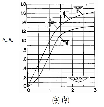
Where Ra and Rb are the panel edge fixity coefficients taken from the following figure

Where ta is the thickness of the stiffener along edge a and tb is the thickness of the stiffener along edge b. The different lines are for single or double back to back L stiffeners.
We have digitized this graph and incorporated it into the panel shear buckling spreadsheet here:
More to follow on dealing with calculated buckling allowables above the material elastic limit.
To try our free Stress Analysis Engineering Spreadsheets click below
To try our Add-in for Microsoft Excel for Windows click below


Comment On This Post