naca-report-814

- Version
- 189 Downloads
- 490.23 KB File Size
- 1 File Count
- August 31, 2016 Create Date
- August 31, 2016 Last Updated
National Advisory Committee for Aeronautics, Report - A General Representation for Axial Flow Fans and Turbines

The general representation of fan and turbine arrangements on
a single classification chart is presented that is made possible by
a particular definition of the stage of an arialflow fan or tur-
bine. Sere-ral unconrentional fan and turbine arrangements
are indicated and the applications of these arrangements are
discussed.
A study of the idealized two—dimensional blade arrange-
ments of axial-flow fans and turbines, or turbomachines,
indicates that, on the basis of a certain definition of the tur-
bomachine stage, various fan and turbine arrangements can
be represented on a single chart. This report presents a
definition of the turbomachine stage and the resulting classi-
fication chart, which was developed from an analysis of the
general velocity diagram for the fan or turbine stage. Some
unconventional fan and turbine arrangements are indicated
in the chart; these arrangements and some possible applica-
tions are discussed. Turbomachines having variable axial-
flow area are shown to be amenable to the same general
representation.
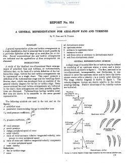
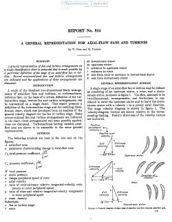
A single stage of an axial-flow fan or turbine may be defined
as consisting of an upstream stator, a rotor, and a down-
stream stator, as shown in figure 1. The flow, assumed to be
two—dimensional, incompressible, and frictionless, is con-
sidered to enter the upstream stator and to leave the down-
stream stator with a velocity r in a piner axial direction.
The stage velocity diagram is shown in figure 1. The
velocity—diagram vectors are shown relative to the corres-
ponding blading. Positive directions of the velocity vectors
are indicated.
The velocity-diagram parameters used in the stage analysis
are a: and y. The peripheral speed of the rotor is denoted by
u. The quantity 2: represents the ratio of the rotor-entrance
relative tangential—velocity component to the rotor peripheral
speed. The quantity 3/ represents the ratio of the rotor-exit
relative tangential-velocity componentto the rotor peripheral
speed. In figure 1, the upstream stator imparts a tangential-
velocity component (r—1)u to the fluid. Relative to the
rotor, the incoming tangential-velocity component is mu and
the outgoing tangential-velocity component is yu. The
downstream stator removes the tangential—velocity com-
ponent (gr-Du from the fluid.
| File | Action |
|---|---|
| naca-report-814 A General Representation for Axial Flow Fans and Turbines.pdf | Download |

Comment On This Post