17,005 Documents in our Technical Library
2727417 Total Downloads

Newest Additions

NASA-RP-1060 Subsonic Aircraft: Evolution and the Matching of Size to Performance
AA-CP-20212-001
AA-CP-20212-001
ADPO10769 Occurrence of Corrosion in Airframes
The purpose of this lecture is to provide an overview ...
MIL-STD-1759 Rivets and Rivet Type Fasteners Preferred for Design
The purpose of this book form standard is to provide ...
MIL-STD-810G Environmental Engineering Considerations and Laboratory Tests
This standard contains materiel acquisition program planning and engineering direction ...

naca-tn-251

  • Version
  • 140 Downloads
  • 177.27 KB File Size
  • 1 File Count
  • November 4, 2016 Create Date
  • November 4, 2016 Last Updated
Scroll for Details

National Advisory Committee for Aeronautics, Technical Notes - The Effect of Tube Length Upon the Recorded Pressured from a Pair of Static Orifices in a Wing Panel
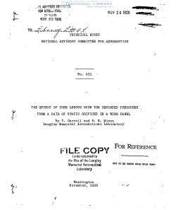
naca-tn-251-the-effect-of-tube-length-upon-the-recorded-pressured-from-a-pair-of-static-orifices-in-a-wing-panel-1

This investigation was instituted to determine the effect
of tubing length upon the indicated pressure values as ascer—I
tained in the pressure distribution measurements upon the PWLQ.
The purpose is to determine the percentage of error in the
pressure readings which might be caused by various lengths of
tubing between the pressure orifices and the pressure cell at
the manometer.

Measurements show that the shortest distance between an
orifice and its corresponding pressure cell on the PWLQ airplane
is 4 ft. 9 in., this orifice being No.4 UyR' which is located
on the upper surface of the right upper wing panel adjacent to
the center section strut fittings. The longest distance, 18
feet, is between the outermost and rearmost orifice in the left
elevator and its corresponding pressure cell.

In order to simulate the conditions which will be found in
the pressure distribution investigation on the PW49 in a quick
and convenient manner, pressure pads of the type employed in
the pressure distribution investigation on the Los Angeles were
installed on the upper and lower surfaces of the lower right
wing panel of a JNS—l airplane. The positions of these pads
were 32 in. out from the fuselage and 20% of the chord back from
the entering edge. These pressure openings were connected di—
rectly to one pressure cell on a recording instrument through a
tubing length of 5 ft. Into these direct lines a narrow Y was
introduced which permitted-a second pressure line to be carried
to a second pressure cell on the same recording instrument
through three different lengths of tubingi. 15, 25 and 50 ft.
This tubing was.installed in the rear of the fuselage with as
few turns as possible and these of a relatively large radius.

FileAction
naca-tn-251 The Effect of Tube Length Upon the Recorded Pressured from a Pair of Static Orifices in a Wing Panel.pdfDownload 

Comment On This Post

Your email address will not be published. Required fields are marked *

naca-tn-251

  • Version
  • 140 Downloads
  • 177.27 KB File Size
  • 1 File Count
  • November 4, 2016 Create Date
  • November 4, 2016 Last Updated
Scroll for Details

National Advisory Committee for Aeronautics, Technical Notes - The Effect of Tube Length Upon the Recorded Pressured from a Pair of Static Orifices in a Wing Panel

naca-tn-251-the-effect-of-tube-length-upon-the-recorded-pressured-from-a-pair-of-static-orifices-in-a-wing-panel-1

This investigation was instituted to determine the effect
of tubing length upon the indicated pressure values as ascer—I
tained in the pressure distribution measurements upon the PWLQ.
The purpose is to determine the percentage of error in the
pressure readings which might be caused by various lengths of
tubing between the pressure orifices and the pressure cell at
the manometer.

Measurements show that the shortest distance between an
orifice and its corresponding pressure cell on the PWLQ airplane
is 4 ft. 9 in., this orifice being No.4 UyR' which is located
on the upper surface of the right upper wing panel adjacent to
the center section strut fittings. The longest distance, 18
feet, is between the outermost and rearmost orifice in the left
elevator and its corresponding pressure cell.

In order to simulate the conditions which will be found in
the pressure distribution investigation on the PW49 in a quick
and convenient manner, pressure pads of the type employed in
the pressure distribution investigation on the Los Angeles were
installed on the upper and lower surfaces of the lower right
wing panel of a JNS—l airplane. The positions of these pads
were 32 in. out from the fuselage and 20% of the chord back from
the entering edge. These pressure openings were connected di—
rectly to one pressure cell on a recording instrument through a
tubing length of 5 ft. Into these direct lines a narrow Y was
introduced which permitted-a second pressure line to be carried
to a second pressure cell on the same recording instrument
through three different lengths of tubingi. 15, 25 and 50 ft.
This tubing was.installed in the rear of the fuselage with as
few turns as possible and these of a relatively large radius.

FileAction
naca-tn-251 The Effect of Tube Length Upon the Recorded Pressured from a Pair of Static Orifices in a Wing Panel.pdfDownload 
17,005 Documents in our Technical Library
2727417 Total Downloads

Search The Technical Library

Newest Additions

NASA-RP-1060 Subsonic Aircraft: Evolution and the Matching of Size to Performance
AA-CP-20212-001
AA-CP-20212-001
ADPO10769 Occurrence of Corrosion in Airframes
The purpose of this lecture is to provide an overview ...
MIL-STD-1759 Rivets and Rivet Type Fasteners Preferred for Design
The purpose of this book form standard is to provide ...
MIL-STD-810G Environmental Engineering Considerations and Laboratory Tests
This standard contains materiel acquisition program planning and engineering direction ...