17,005 Documents in our Technical Library
2727423 Total Downloads

Newest Additions

NASA-RP-1060 Subsonic Aircraft: Evolution and the Matching of Size to Performance
AA-CP-20212-001
AA-CP-20212-001
ADPO10769 Occurrence of Corrosion in Airframes
The purpose of this lecture is to provide an overview ...
MIL-STD-1759 Rivets and Rivet Type Fasteners Preferred for Design
The purpose of this book form standard is to provide ...
MIL-STD-810G Environmental Engineering Considerations and Laboratory Tests
This standard contains materiel acquisition program planning and engineering direction ...

naca-tn-3156

  • Version
  • 141 Downloads
  • 1.55 MB File Size
  • 1 File Count
  • January 23, 2017 Create Date
  • January 23, 2017 Last Updated
Scroll for Details

National Advisory Committee for Aeronautics, Technical Notes - Charts for Estimating Tail Rotor Contribution to Helicopter Direction Stability and Control in Low Speed Flight
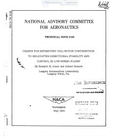
Theoretically derived charts and equations are presented by which
tail-rotor design studies of directional trim and control response at
low forward speed can be conveniently made. The charts can also be used
to obtain the main—rotor stability derivatives of thrust with respect to
collective pitch and angle of attack at low forward speeds.

The use of the charts and equations for tail-rotor design studies
is illustrated. Comparisons between theoretical and experimental results
are presented.

The charts indicate, and flight tests confirm, that the region of
vortex roughness which is familiar for the main rotor is also encountered
by the tail rotor, and that prolonged operation at the corresponding
flight c0nditions would be difficult.

The tail rotor of a conventionally powered single-rotor helicopter
has two purposes — to counteract the rotor torque and fuselage yawing
moments and to maneuver the helicopter directionally. Preliminary
flying— quality studies have indicated.a minimum desirable response of
3° yaw in the first second following a 1—inch step displacement of the
pedals while hovering in zero wind. In addition to indicating a mini—
mum desirable response value, these studies have also indicated the
existence of a maximum desirable response value. When large pedal fric—
tion and out-of—trim forces are present, the maximum desirable response
value is indicated to be approximately 10° of yaw in the first second
following a 1-inch step displacement of the pedals while hovering in
zero wind. When pedal friction and out-of—trim forces are relatively
small, a maximum desirable value of 2'to untimes as large as the 10° value
is indicated.

Some of—these flying- quality indications are incorporated in the
flying-quality requirements of reference 1. In addition, reference 1
calls for the ability of average—sized helicopters to make a complete
turn over a spot while hovering in a 50-knot wind and, while trimmed
at the most critical yaw angle, to be able to achieve at least 5° of
yaw in the first second following full deflection er the pedals in the
critical direction; Other flying—quality and stability studies have
indicated that careful design is frequently required to satisfy these
criteria without unnecessary sacrifice in weight, rotor clearances, or
other factors. Tail rotors for Jet—powered helicopters, for example, are
of minimum size inasmuch as their primary purpose is to—provide control,
and unless specifically designed to do so, might not fulfill all of these
criteria.

FileAction
naca-tn-3156 Charts for Estimating Tail Rotor Contribution to Helicopter Direction Stability and Control in Low Speed Flight.pdfDownload 

Comment On This Post

Your email address will not be published. Required fields are marked *

naca-tn-3156

  • Version
  • 141 Downloads
  • 1.55 MB File Size
  • 1 File Count
  • January 23, 2017 Create Date
  • January 23, 2017 Last Updated
Scroll for Details

National Advisory Committee for Aeronautics, Technical Notes - Charts for Estimating Tail Rotor Contribution to Helicopter Direction Stability and Control in Low Speed Flight

Theoretically derived charts and equations are presented by which
tail-rotor design studies of directional trim and control response at
low forward speed can be conveniently made. The charts can also be used
to obtain the main—rotor stability derivatives of thrust with respect to
collective pitch and angle of attack at low forward speeds.

The use of the charts and equations for tail-rotor design studies
is illustrated. Comparisons between theoretical and experimental results
are presented.

The charts indicate, and flight tests confirm, that the region of
vortex roughness which is familiar for the main rotor is also encountered
by the tail rotor, and that prolonged operation at the corresponding
flight c0nditions would be difficult.

The tail rotor of a conventionally powered single-rotor helicopter
has two purposes — to counteract the rotor torque and fuselage yawing
moments and to maneuver the helicopter directionally. Preliminary
flying— quality studies have indicated.a minimum desirable response of
3° yaw in the first second following a 1—inch step displacement of the
pedals while hovering in zero wind. In addition to indicating a mini—
mum desirable response value, these studies have also indicated the
existence of a maximum desirable response value. When large pedal fric—
tion and out-of—trim forces are present, the maximum desirable response
value is indicated to be approximately 10° of yaw in the first second
following a 1-inch step displacement of the pedals while hovering in
zero wind. When pedal friction and out-of—trim forces are relatively
small, a maximum desirable value of 2'to untimes as large as the 10° value
is indicated.

Some of—these flying- quality indications are incorporated in the
flying-quality requirements of reference 1. In addition, reference 1
calls for the ability of average—sized helicopters to make a complete
turn over a spot while hovering in a 50-knot wind and, while trimmed
at the most critical yaw angle, to be able to achieve at least 5° of
yaw in the first second following full deflection er the pedals in the
critical direction; Other flying—quality and stability studies have
indicated that careful design is frequently required to satisfy these
criteria without unnecessary sacrifice in weight, rotor clearances, or
other factors. Tail rotors for Jet—powered helicopters, for example, are
of minimum size inasmuch as their primary purpose is to—provide control,
and unless specifically designed to do so, might not fulfill all of these
criteria.

FileAction
naca-tn-3156 Charts for Estimating Tail Rotor Contribution to Helicopter Direction Stability and Control in Low Speed Flight.pdfDownload 
17,005 Documents in our Technical Library
2727423 Total Downloads

Search The Technical Library

Newest Additions

NASA-RP-1060 Subsonic Aircraft: Evolution and the Matching of Size to Performance
AA-CP-20212-001
AA-CP-20212-001
ADPO10769 Occurrence of Corrosion in Airframes
The purpose of this lecture is to provide an overview ...
MIL-STD-1759 Rivets and Rivet Type Fasteners Preferred for Design
The purpose of this book form standard is to provide ...
MIL-STD-810G Environmental Engineering Considerations and Laboratory Tests
This standard contains materiel acquisition program planning and engineering direction ...