17,005 Documents in our Technical Library
2727377 Total Downloads

Newest Additions

NASA-RP-1060 Subsonic Aircraft: Evolution and the Matching of Size to Performance
AA-CP-20212-001
AA-CP-20212-001
ADPO10769 Occurrence of Corrosion in Airframes
The purpose of this lecture is to provide an overview ...
MIL-STD-1759 Rivets and Rivet Type Fasteners Preferred for Design
The purpose of this book form standard is to provide ...
MIL-STD-810G Environmental Engineering Considerations and Laboratory Tests
This standard contains materiel acquisition program planning and engineering direction ...

naca-tn-333

  • Version
  • 184 Downloads
  • 735.40 KB File Size
  • 1 File Count
  • November 4, 2016 Create Date
  • November 4, 2016 Last Updated
Scroll for Details

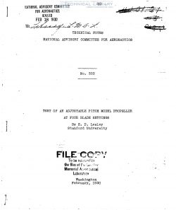
National Advisory Committee for Aeronautics, Technical Notes - Test of an Adjustable Pitch Model Propeller at Four Blade Settings
naca-tn-333-test-of-an-adjustable-pitch-model-propeller-at-four-blade-settings-1

This note describes tests of an adjustable blade metal model
propeller, both in a free wind stream and in combination with a__
model fuselage, at four settings of the blades. The model pro—
peller is designed for a uniform nominal pitch/diameter ratio of
.7 and the blade settings used correspond to nominal pitch/
diameter ratios of .5, .7, .9, and 1.1 at the .6 radius.

The tests show that propellers of this type may be considy
erably changed in setting from the designed pitch angles and yet
give excellent performance.

The efficiency realized and power absorbed when blades are
set at other than the designed angle,.are little different than
would be obtained from a propeller with uniform pitch equal to
the mean pitch of the propeller under test.

The adjustable blade metal propeller is usually designed to
have the blades set at such an angle as will provide a somewhat
uniform pitch along the radius. It has been shown that (Refer—
ence l), in a free wind stream, while such a propeller gives the
greatest efficiency there may be considerable variation in pitch
as distributed along the radius without serious efficiency loss.
'It has also been shown that (Reference 1), in combination with a
slipstream obstruction, a prOpeller with a radial pitch distribus
tion similar to the radial distribution_of velocity through the
propeller plane, gives superior results. The present tests give
some further confirmation of the above conclusions.

The model propeller chosen for these tests was pr0peller A
of Reference 1. The blade form is shown in Figure l. The model
has a uniform nominal pitch/diameter ratio of .7 when set at the
angles shown. For a nominal pitch/diameter ratio (at .6 radius)
of .5, the blade angles are decreased 5.60. For a pitch/diameter
ratio of .9 they are increased 5.10. For a pitch/diameter ratio
of l.l they are increased 9.90.

FileAction
naca-tn-333 Test of an Adjustable Pitch Model Propeller at Four Blade Settings.pdfDownload 

Comment On This Post

Your email address will not be published. Required fields are marked *

naca-tn-333

  • Version
  • 184 Downloads
  • 735.40 KB File Size
  • 1 File Count
  • November 4, 2016 Create Date
  • November 4, 2016 Last Updated
Scroll for Details

National Advisory Committee for Aeronautics, Technical Notes - Test of an Adjustable Pitch Model Propeller at Four Blade Settings

naca-tn-333-test-of-an-adjustable-pitch-model-propeller-at-four-blade-settings-1

This note describes tests of an adjustable blade metal model
propeller, both in a free wind stream and in combination with a__
model fuselage, at four settings of the blades. The model pro—
peller is designed for a uniform nominal pitch/diameter ratio of
.7 and the blade settings used correspond to nominal pitch/
diameter ratios of .5, .7, .9, and 1.1 at the .6 radius.

The tests show that propellers of this type may be considy
erably changed in setting from the designed pitch angles and yet
give excellent performance.

The efficiency realized and power absorbed when blades are
set at other than the designed angle,.are little different than
would be obtained from a propeller with uniform pitch equal to
the mean pitch of the propeller under test.

The adjustable blade metal propeller is usually designed to
have the blades set at such an angle as will provide a somewhat
uniform pitch along the radius. It has been shown that (Refer—
ence l), in a free wind stream, while such a propeller gives the
greatest efficiency there may be considerable variation in pitch
as distributed along the radius without serious efficiency loss.
'It has also been shown that (Reference 1), in combination with a
slipstream obstruction, a prOpeller with a radial pitch distribus
tion similar to the radial distribution_of velocity through the
propeller plane, gives superior results. The present tests give
some further confirmation of the above conclusions.

The model propeller chosen for these tests was pr0peller A
of Reference 1. The blade form is shown in Figure l. The model
has a uniform nominal pitch/diameter ratio of .7 when set at the
angles shown. For a nominal pitch/diameter ratio (at .6 radius)
of .5, the blade angles are decreased 5.60. For a pitch/diameter
ratio of .9 they are increased 5.10. For a pitch/diameter ratio
of l.l they are increased 9.90.

FileAction
naca-tn-333 Test of an Adjustable Pitch Model Propeller at Four Blade Settings.pdfDownload 
17,005 Documents in our Technical Library
2727377 Total Downloads

Search The Technical Library

Newest Additions

NASA-RP-1060 Subsonic Aircraft: Evolution and the Matching of Size to Performance
AA-CP-20212-001
AA-CP-20212-001
ADPO10769 Occurrence of Corrosion in Airframes
The purpose of this lecture is to provide an overview ...
MIL-STD-1759 Rivets and Rivet Type Fasteners Preferred for Design
The purpose of this book form standard is to provide ...
MIL-STD-810G Environmental Engineering Considerations and Laboratory Tests
This standard contains materiel acquisition program planning and engineering direction ...