17,005 Documents in our Technical Library
2727380 Total Downloads

Newest Additions

NASA-RP-1060 Subsonic Aircraft: Evolution and the Matching of Size to Performance
AA-CP-20212-001
AA-CP-20212-001
ADPO10769 Occurrence of Corrosion in Airframes
The purpose of this lecture is to provide an overview ...
MIL-STD-1759 Rivets and Rivet Type Fasteners Preferred for Design
The purpose of this book form standard is to provide ...
MIL-STD-810G Environmental Engineering Considerations and Laboratory Tests
This standard contains materiel acquisition program planning and engineering direction ...

naca-tn-401

  • Version
  • 136 Downloads
  • 1,018.16 KB File Size
  • 1 File Count
  • November 24, 2016 Create Date
  • November 24, 2016 Last Updated
Scroll for Details

National Advisory Committee for Aeronautics, Technical Notes - Tests of NACA Airfoils in the Variable Density Wind Tunnel, Series 44 & 64
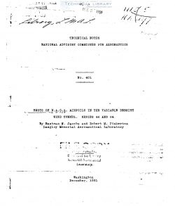
naca-tn-401-tests-of-naca-airfoils-in-the-variable-density-wind-tunnel-series-44-64-1

This note is one of a series.covering an investiga—
tiOn of a number of related airfoils. It presents the
results obtained from tests in the N.A.C.A.{V§riableqfien-
sity indlrunnel of.two groups of six airfo ls each. One
gro , the 44 series, has a maximum mean camber of 4 per
cent of the chord at a yoeition 0.4 of the chord behind
the leading edge and the other group, the 64 series, has
a maximum mean camber of 6 per cent of the chord at the
same position. The members within each group differ only
in maximum thickness, the maximum thickness/chord ratios
being:-G.06, 0.09, 0.12, 0.15, 0.18‘and-O.21. The results
are analyzed with a View to indicating the variation of
the aerodynamic characteristics with profile'thickness for
airfoils-having a certain mean camber line form.

_ A large number of related airfoils are being tested
in thg/v’ariable-iyensity'yind finnei of the National Advi—
sory ommittee or Aeronautics with.a View to establish—
ing the relation between the geometric and the aerodynamic
characteristics of airfoils at a high value of the Reynolds
Number. The method employed to develop the airfoils hav—
ing varying geometric preperties is described in detail
in references 1 and 3. Briefly, the profiles are obtained
by combining certain thickness forms (reference 1) with
several related mean camber line formsyflfleference B ). The
airfoils are designated by a number of four digits: the
first indicates the maximum mean camber; the second, the
position of maximum mean camber; and the last two, the
maximum thickness.

Preliminary results already published include the
tests on six symmetrical N.A.C.A. airfoils, 00 series
(reference 1); the tests on'the 43 and 63.series (refer—
ence 2), and the tests on the 45 and 65 series. (Refer-
ence 5.) Similar publications'will_follow-as the tests
are made.

This note-presents the results of tests of two series
of six airfoils each, the airfoils of each series having
the same thicL ness forms as those of the symmetrical series
(reference 1) but having curved instead of straight mean
camber lines. All 12 airfoils have mean camber lines of
such a form that the position of the maximum mean camber
is 0.4 of the chord behind the leading edge. Six of the
airfoils, the 44 series, have a maximum mean camber of 4
per'ccnt of the chord, and the other six, the 64 series.
have a maximum mean camber of-B per cent:"

FileAction
naca-tn-401 Tests of NACA Airfoils in the Variable Density Wind Tunnel, Series 44 & 64.pdfDownload 

Comment On This Post

Your email address will not be published. Required fields are marked *

naca-tn-401

  • Version
  • 136 Downloads
  • 1,018.16 KB File Size
  • 1 File Count
  • November 24, 2016 Create Date
  • November 24, 2016 Last Updated
Scroll for Details

National Advisory Committee for Aeronautics, Technical Notes - Tests of NACA Airfoils in the Variable Density Wind Tunnel, Series 44 & 64

naca-tn-401-tests-of-naca-airfoils-in-the-variable-density-wind-tunnel-series-44-64-1

This note is one of a series.covering an investiga—
tiOn of a number of related airfoils. It presents the
results obtained from tests in the N.A.C.A.{V§riableqfien-
sity indlrunnel of.two groups of six airfo ls each. One
gro , the 44 series, has a maximum mean camber of 4 per
cent of the chord at a yoeition 0.4 of the chord behind
the leading edge and the other group, the 64 series, has
a maximum mean camber of 6 per cent of the chord at the
same position. The members within each group differ only
in maximum thickness, the maximum thickness/chord ratios
being:-G.06, 0.09, 0.12, 0.15, 0.18‘and-O.21. The results
are analyzed with a View to indicating the variation of
the aerodynamic characteristics with profile'thickness for
airfoils-having a certain mean camber line form.

_ A large number of related airfoils are being tested
in thg/v’ariable-iyensity'yind finnei of the National Advi—
sory ommittee or Aeronautics with.a View to establish—
ing the relation between the geometric and the aerodynamic
characteristics of airfoils at a high value of the Reynolds
Number. The method employed to develop the airfoils hav—
ing varying geometric preperties is described in detail
in references 1 and 3. Briefly, the profiles are obtained
by combining certain thickness forms (reference 1) with
several related mean camber line formsyflfleference B ). The
airfoils are designated by a number of four digits: the
first indicates the maximum mean camber; the second, the
position of maximum mean camber; and the last two, the
maximum thickness.

Preliminary results already published include the
tests on six symmetrical N.A.C.A. airfoils, 00 series
(reference 1); the tests on'the 43 and 63.series (refer—
ence 2), and the tests on the 45 and 65 series. (Refer-
ence 5.) Similar publications'will_follow-as the tests
are made.

This note-presents the results of tests of two series
of six airfoils each, the airfoils of each series having
the same thicL ness forms as those of the symmetrical series
(reference 1) but having curved instead of straight mean
camber lines. All 12 airfoils have mean camber lines of
such a form that the position of the maximum mean camber
is 0.4 of the chord behind the leading edge. Six of the
airfoils, the 44 series, have a maximum mean camber of 4
per'ccnt of the chord, and the other six, the 64 series.
have a maximum mean camber of-B per cent:"

FileAction
naca-tn-401 Tests of NACA Airfoils in the Variable Density Wind Tunnel, Series 44 & 64.pdfDownload 
17,005 Documents in our Technical Library
2727380 Total Downloads

Search The Technical Library

Newest Additions

NASA-RP-1060 Subsonic Aircraft: Evolution and the Matching of Size to Performance
AA-CP-20212-001
AA-CP-20212-001
ADPO10769 Occurrence of Corrosion in Airframes
The purpose of this lecture is to provide an overview ...
MIL-STD-1759 Rivets and Rivet Type Fasteners Preferred for Design
The purpose of this book form standard is to provide ...
MIL-STD-810G Environmental Engineering Considerations and Laboratory Tests
This standard contains materiel acquisition program planning and engineering direction ...