17,005 Documents in our Technical Library
2727387 Total Downloads

Newest Additions

NASA-RP-1060 Subsonic Aircraft: Evolution and the Matching of Size to Performance
AA-CP-20212-001
AA-CP-20212-001
ADPO10769 Occurrence of Corrosion in Airframes
The purpose of this lecture is to provide an overview ...
MIL-STD-1759 Rivets and Rivet Type Fasteners Preferred for Design
The purpose of this book form standard is to provide ...
MIL-STD-810G Environmental Engineering Considerations and Laboratory Tests
This standard contains materiel acquisition program planning and engineering direction ...

naca-tn-524

  • Version
  • 153 Downloads
  • 602.83 KB File Size
  • 1 File Count
  • November 25, 2016 Create Date
  • November 25, 2016 Last Updated
Scroll for Details

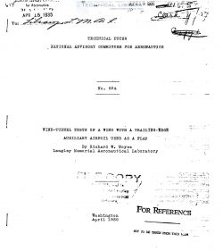
National Advisory Committee for Aeronautics, Technical Notes - Wind Tunnel Tests of a Wing with a Trailing Edge Auxiliary Airfoil Used as a Flap
naca-tn-524-wind-tunnel-tests-of-a-wing-with-a-trailing-edge-auxiliary-airfoil-used-as-a-flap-1

This report gives the characteristics of a wing with
an auxiliary airfoil mounted near its trailing edge and"
used as a flap. The tests were made with_a 10 by 60 inch
Clark Y main airfoil and an N.A.C.A. 0012 flap having a
chord equal to 15 percent of the main wing chord. The
axis of the flap in all cases was on the flap chord and
20 percent back from its leading edge.

The optimum location of the flap axis relative to the
main wing for maximum lift was found to be 1.25 percent of
the main wing chord behind the trailing edge and 2.5 per-
cent below the chord. In this position CLmax was in-
creased from 1.250 (for the plain wing) to 1.810 at 45° dee
flection of the flap and CDmin was decreased from 0.0155
to 0.0146 at —5° deflection, the coefficient in each case
being based on the sum of the flap and wing areas. No
serious adverse change in lateral stability was found to
result from the use of the flap in the optimum position.

In most of the cases where flaps are employed to in-
crease the maximum lift of a wing they are so constructed
as to retract into or become a part of the main wing when
in their natural or low—drag attitude. A less common type
consists of an auxiliary airfoil which remains external to
the main wing at all times. This latter type of flap has
been used on certain Junkers airplanes in Germany and tests
have been made in this country (reference 1) on a somewhat
similar installation known as the Wragg compound wing.

The present report gives the results of tests made
by the N.A.C.A. on a Clark Y wing with an auxiliary air~
foil, 15 percent of the wing chord wide, mounted in sev—
eral pesitions near the trailing edge. The data were ob-
tained in the course of a comprehensive investigation of
auxiliary airfoils for use as ailerons and for this reason
the information relative to their use as a high-lift de—
vice is not cemplete at all test positions. The scope of
the tests. however, included the determination of the max-
imum lift and minimum drag ebtainabfie and the best value
of the climb criterion (L/D at CL = 0.7) at nearly all
the positions tested. In addition, more detailed lift,
drag, center~of~pressure. and lateral—stability data were
obtained with the flap in the most favorable location.
The range of locations of the flap axis was from 70 to 110
percent of the wing chord and from O to 80 percent below
the wing chord. This range includes the flap positions
used by both Junkers and Wragg.

FileAction
naca-tn-524 Wind Tunnel Tests of a Wing with a Trailing Edge Auxiliary Airfoil Used as a Flap.pdfDownload 

Comment On This Post

Your email address will not be published. Required fields are marked *

naca-tn-524

  • Version
  • 153 Downloads
  • 602.83 KB File Size
  • 1 File Count
  • November 25, 2016 Create Date
  • November 25, 2016 Last Updated
Scroll for Details

National Advisory Committee for Aeronautics, Technical Notes - Wind Tunnel Tests of a Wing with a Trailing Edge Auxiliary Airfoil Used as a Flap

naca-tn-524-wind-tunnel-tests-of-a-wing-with-a-trailing-edge-auxiliary-airfoil-used-as-a-flap-1

This report gives the characteristics of a wing with
an auxiliary airfoil mounted near its trailing edge and"
used as a flap. The tests were made with_a 10 by 60 inch
Clark Y main airfoil and an N.A.C.A. 0012 flap having a
chord equal to 15 percent of the main wing chord. The
axis of the flap in all cases was on the flap chord and
20 percent back from its leading edge.

The optimum location of the flap axis relative to the
main wing for maximum lift was found to be 1.25 percent of
the main wing chord behind the trailing edge and 2.5 per-
cent below the chord. In this position CLmax was in-
creased from 1.250 (for the plain wing) to 1.810 at 45° dee
flection of the flap and CDmin was decreased from 0.0155
to 0.0146 at —5° deflection, the coefficient in each case
being based on the sum of the flap and wing areas. No
serious adverse change in lateral stability was found to
result from the use of the flap in the optimum position.

In most of the cases where flaps are employed to in-
crease the maximum lift of a wing they are so constructed
as to retract into or become a part of the main wing when
in their natural or low—drag attitude. A less common type
consists of an auxiliary airfoil which remains external to
the main wing at all times. This latter type of flap has
been used on certain Junkers airplanes in Germany and tests
have been made in this country (reference 1) on a somewhat
similar installation known as the Wragg compound wing.

The present report gives the results of tests made
by the N.A.C.A. on a Clark Y wing with an auxiliary air~
foil, 15 percent of the wing chord wide, mounted in sev—
eral pesitions near the trailing edge. The data were ob-
tained in the course of a comprehensive investigation of
auxiliary airfoils for use as ailerons and for this reason
the information relative to their use as a high-lift de—
vice is not cemplete at all test positions. The scope of
the tests. however, included the determination of the max-
imum lift and minimum drag ebtainabfie and the best value
of the climb criterion (L/D at CL = 0.7) at nearly all
the positions tested. In addition, more detailed lift,
drag, center~of~pressure. and lateral—stability data were
obtained with the flap in the most favorable location.
The range of locations of the flap axis was from 70 to 110
percent of the wing chord and from O to 80 percent below
the wing chord. This range includes the flap positions
used by both Junkers and Wragg.

FileAction
naca-tn-524 Wind Tunnel Tests of a Wing with a Trailing Edge Auxiliary Airfoil Used as a Flap.pdfDownload 
17,005 Documents in our Technical Library
2727387 Total Downloads

Search The Technical Library

Newest Additions

NASA-RP-1060 Subsonic Aircraft: Evolution and the Matching of Size to Performance
AA-CP-20212-001
AA-CP-20212-001
ADPO10769 Occurrence of Corrosion in Airframes
The purpose of this lecture is to provide an overview ...
MIL-STD-1759 Rivets and Rivet Type Fasteners Preferred for Design
The purpose of this book form standard is to provide ...
MIL-STD-810G Environmental Engineering Considerations and Laboratory Tests
This standard contains materiel acquisition program planning and engineering direction ...