17,005 Documents in our Technical Library
2727416 Total Downloads

Newest Additions

NASA-RP-1060 Subsonic Aircraft: Evolution and the Matching of Size to Performance
AA-CP-20212-001
AA-CP-20212-001
ADPO10769 Occurrence of Corrosion in Airframes
The purpose of this lecture is to provide an overview ...
MIL-STD-1759 Rivets and Rivet Type Fasteners Preferred for Design
The purpose of this book form standard is to provide ...
MIL-STD-810G Environmental Engineering Considerations and Laboratory Tests
This standard contains materiel acquisition program planning and engineering direction ...

naca-tn-545

  • Version
  • 179 Downloads
  • 789.97 KB File Size
  • 1 File Count
  • November 25, 2016 Create Date
  • November 25, 2016 Last Updated
Scroll for Details

National Advisory Committee for Aeronautics, Technical Notes - Tank Tests of a Model of a Flying Boat Hull Having a Longitudinally Concave Planing Bottom
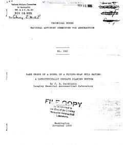
naca-tn-545-tank-tests-of-a-model-of-a-flying-boat-hull-having-a-longitudinally-concave-planing-bottom-1

The portion of a flying—boat hull or seaplane float
forward of the step supports a large part of the total
load during take—off and receives the major portion of the
impact in alighting. Its'propér form is a compromise re~
sulting from considerations of water resistance, drag'fi"
flight, and shock—absorbing qualities. The most common
solution is fundamentally a V—bottom planing surface having
a straight or slightly convex profile near the step.

As a part of a compre_hensive study of planing phenom-
ena. Sottorf (reference 1) investigated two planing sur-
faces that were transversely flat but longitudinally cone
cave. The surfaces were tested at various angles of trim
for a load coefficient CA of 0.65 and a Speed coefficient-
of 5.55.

The ratios of longitudinal radius to beam
were 38.3 and 20, and the load—resistance ratios at the
best angle of trim were found to be 10 and 16 percent high~
er, respectively, than_that of a plane surface. The trims
ming moment about the trailing edge and the height of the
spray were reduced.

Tank tests of N.A.G.A. model ll-A demonstrated the
superiority of a straight profile for the planing bottom
of a flying boat over the convex profile of N.A.C.A. mod—
el.ll in regard to water resistance (reference 2). Tests
of a model of the U.S. Navy PH~1 flying boat (reference 3)
showed that a small downward drop or "hook" at the step
caused the resistance of this hull to be slightly lower.

A logical extension of these tests is the investigation oi
a model in which a generally concave profile of the plan-
ing bottom would be compared with a straight profile. Ac-
cordingly, a concave planing bottom was introduced into
N.A.C.A. model 11—0 and the resulting form was tested in
the N.A.C.A. tank as model ll-B.

FileAction
naca-tn-545 Tank Tests of a Model of a Flying Boat Hull Having a Longitudinally Concave Planing Bottom.pdfDownload 

Comment On This Post

Your email address will not be published. Required fields are marked *

naca-tn-545

  • Version
  • 179 Downloads
  • 789.97 KB File Size
  • 1 File Count
  • November 25, 2016 Create Date
  • November 25, 2016 Last Updated
Scroll for Details

National Advisory Committee for Aeronautics, Technical Notes - Tank Tests of a Model of a Flying Boat Hull Having a Longitudinally Concave Planing Bottom

naca-tn-545-tank-tests-of-a-model-of-a-flying-boat-hull-having-a-longitudinally-concave-planing-bottom-1

The portion of a flying—boat hull or seaplane float
forward of the step supports a large part of the total
load during take—off and receives the major portion of the
impact in alighting. Its'propér form is a compromise re~
sulting from considerations of water resistance, drag'fi"
flight, and shock—absorbing qualities. The most common
solution is fundamentally a V—bottom planing surface having
a straight or slightly convex profile near the step.

As a part of a compre_hensive study of planing phenom-
ena. Sottorf (reference 1) investigated two planing sur-
faces that were transversely flat but longitudinally cone
cave. The surfaces were tested at various angles of trim
for a load coefficient CA of 0.65 and a Speed coefficient-
of 5.55.

The ratios of longitudinal radius to beam
were 38.3 and 20, and the load—resistance ratios at the
best angle of trim were found to be 10 and 16 percent high~
er, respectively, than_that of a plane surface. The trims
ming moment about the trailing edge and the height of the
spray were reduced.

Tank tests of N.A.G.A. model ll-A demonstrated the
superiority of a straight profile for the planing bottom
of a flying boat over the convex profile of N.A.C.A. mod—
el.ll in regard to water resistance (reference 2). Tests
of a model of the U.S. Navy PH~1 flying boat (reference 3)
showed that a small downward drop or "hook" at the step
caused the resistance of this hull to be slightly lower.

A logical extension of these tests is the investigation oi
a model in which a generally concave profile of the plan-
ing bottom would be compared with a straight profile. Ac-
cordingly, a concave planing bottom was introduced into
N.A.C.A. model 11—0 and the resulting form was tested in
the N.A.C.A. tank as model ll-B.

FileAction
naca-tn-545 Tank Tests of a Model of a Flying Boat Hull Having a Longitudinally Concave Planing Bottom.pdfDownload 
17,005 Documents in our Technical Library
2727416 Total Downloads

Search The Technical Library

Newest Additions

NASA-RP-1060 Subsonic Aircraft: Evolution and the Matching of Size to Performance
AA-CP-20212-001
AA-CP-20212-001
ADPO10769 Occurrence of Corrosion in Airframes
The purpose of this lecture is to provide an overview ...
MIL-STD-1759 Rivets and Rivet Type Fasteners Preferred for Design
The purpose of this book form standard is to provide ...
MIL-STD-810G Environmental Engineering Considerations and Laboratory Tests
This standard contains materiel acquisition program planning and engineering direction ...