17,005 Documents in our Technical Library
2727445 Total Downloads

Newest Additions

NASA-RP-1060 Subsonic Aircraft: Evolution and the Matching of Size to Performance
AA-CP-20212-001
AA-CP-20212-001
ADPO10769 Occurrence of Corrosion in Airframes
The purpose of this lecture is to provide an overview ...
MIL-STD-1759 Rivets and Rivet Type Fasteners Preferred for Design
The purpose of this book form standard is to provide ...
MIL-STD-810G Environmental Engineering Considerations and Laboratory Tests
This standard contains materiel acquisition program planning and engineering direction ...

naca-wr-l-518

  • Version
  • 91 Downloads
  • 274.17 KB File Size
  • 1 File Count
  • April 2, 2017 Create Date
  • April 2, 2017 Last Updated
Scroll for Details

Hydrodynamic Stability Tests of a Model of a Flying Boat and of a Planing Surface Having a Small Downward Projection (Hook) on the Planing Bottom Near the Step
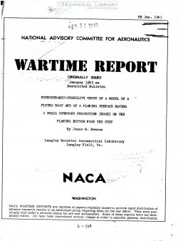
Stability tests of two dynamic models in HACA tank
no. 1 were carried out to investigate briefly the effects
of adding a small projection (hook) on the_p1aning bottom
of the forebody near the step of a seaplane. Tests with
a wedge-ehape- and a half-round projection extending the
full width of the model and extending downward about
eight—tenths of 1 percent of the beam had rather large
effects upon all trim limits and also upon the landing
stability. All trim limits were lowered. about 4° at
high speeds. and the tendency to skip on landing was in-
creased.

INTRODUCTION

The planing bottom of a seaplane of current design
generally has no longitudinal curvature in the forebody
near the step. Tank tests of models (references 1 and 2)
have indicated that some desirable effect upon the resist-
ance and trimming-moment characteristics may be obtained
by use of a small hook at the step. Service trials of a
flying boat fitted with a hooked step have shown very un-
desirable stability characteristics (see reference 2).
particularly at landing; this effect has caused the Bureau
of Aeronautics to discontinue the use of that form of bot-
tom. During tests of dynamic models in NACA tank no. 1..
it has been observed occasionally that relatively small
irregularities on the forebody near the step - for example.
wrinkles in the film used to cover the bottom - caused a
noticeable reduction in the lower trim limit of stability.
'The present tests were carried out to determine the
effect upon stability characteristics of adding a hook at
the step with a view toward reproducing on a model the
landing instability observed by the Bureau of Aeronautics.
The tests were also undertaken to explore the magnitude of
the effect caused by irregularities of the bottom that may
be introduced unintentionally by alterations of a model
during dynamic tests. A simple. wedge-shepe' strip with
the apex forward was attached to the model for obtaining
the stability characteristics of a hook on the forebody.

A half-round strip made from a wooden dowel. which was

1/8 inch in diameter for the model having a beam of 16
inches. was used to simulate an extreme case of wrinkling
in the film used to cover and seal the bottom of the model.
The tests included measurements of the trim limits of sta-
bility and observations of the lending stability.

APPARATUS AND PROCflDURE

Profile and bow views of the model of a flying boat
are included in figure 1. Dimensions of the model are as
follows:

Beam. maximum, inches . . . . . . . . . .14.24 (1.00 beam)
Beam. at step. inches . . . . . . . 13.86 (0.97 beam)
Length of forebcdy (bow to step). inches 51.70 (3.65 beam)
Length. over—all. inches . . . . . . . 124. 05 (8.71 beam)
Angle of dead rise at step. excluding chine flare.

degrees . . . . . . . . . . . . . . . . . . . . . 20
Angle between forebody keel and afterbody keel at step.

degrees . . . . . . . . . . . . . . . . . . . . . 6.8
ling area. square feet . . . . . . . . . . 25.6
Wing span. inches . . . . . . . . . . . . . . . . . . 200
Length of M.A.c. (wing). inches . . . . 20.12
Angle of incidence of wing. H.A.c. to forebody keel,

dagfeea I I l I I I I I I I I l I I I I I I I I I 3-2
Eorizc._ta1 tail area. square feet . . . . . . . . . . 3.51
Pitching moment of inertia. slug—feeta. . . . . . . . 6.9

Distance of c.g. forward of step. inches.From 3.56 to 6.00
Distance of c.g. above forebody keel at step. inches.12.23

The construction of the model is similar to that generally
used in dynamic models for tests at the NACA tank. (see
reference 3 ) A second model. that of a planing surface.
was “god for a part of the tests. The planing surface has
a 223° V—bottom and a beam of 16 inches and is the same as
" ” that describednin.reference 4. Hodifications to the models
and dimensions of the hook and the half-round are.shown in
'figure 2.

FileAction
naca-wr-l-518 Hydrodynamic Stability Tests of a Model of a Flying Boat and of a Planing Surface Having a Small Downward Projection (Hook) on the Planing Bottom Near the Step.pdfDownload 

Comment On This Post

Your email address will not be published. Required fields are marked *

naca-wr-l-518

  • Version
  • 91 Downloads
  • 274.17 KB File Size
  • 1 File Count
  • April 2, 2017 Create Date
  • April 2, 2017 Last Updated
Scroll for Details

Hydrodynamic Stability Tests of a Model of a Flying Boat and of a Planing Surface Having a Small Downward Projection (Hook) on the Planing Bottom Near the Step

Stability tests of two dynamic models in HACA tank
no. 1 were carried out to investigate briefly the effects
of adding a small projection (hook) on the_p1aning bottom
of the forebody near the step of a seaplane. Tests with
a wedge-ehape- and a half-round projection extending the
full width of the model and extending downward about
eight—tenths of 1 percent of the beam had rather large
effects upon all trim limits and also upon the landing
stability. All trim limits were lowered. about 4° at
high speeds. and the tendency to skip on landing was in-
creased.

INTRODUCTION

The planing bottom of a seaplane of current design
generally has no longitudinal curvature in the forebody
near the step. Tank tests of models (references 1 and 2)
have indicated that some desirable effect upon the resist-
ance and trimming-moment characteristics may be obtained
by use of a small hook at the step. Service trials of a
flying boat fitted with a hooked step have shown very un-
desirable stability characteristics (see reference 2).
particularly at landing; this effect has caused the Bureau
of Aeronautics to discontinue the use of that form of bot-
tom. During tests of dynamic models in NACA tank no. 1..
it has been observed occasionally that relatively small
irregularities on the forebody near the step - for example.
wrinkles in the film used to cover the bottom - caused a
noticeable reduction in the lower trim limit of stability.
'The present tests were carried out to determine the
effect upon stability characteristics of adding a hook at
the step with a view toward reproducing on a model the
landing instability observed by the Bureau of Aeronautics.
The tests were also undertaken to explore the magnitude of
the effect caused by irregularities of the bottom that may
be introduced unintentionally by alterations of a model
during dynamic tests. A simple. wedge-shepe' strip with
the apex forward was attached to the model for obtaining
the stability characteristics of a hook on the forebody.

A half-round strip made from a wooden dowel. which was

1/8 inch in diameter for the model having a beam of 16
inches. was used to simulate an extreme case of wrinkling
in the film used to cover and seal the bottom of the model.
The tests included measurements of the trim limits of sta-
bility and observations of the lending stability.

APPARATUS AND PROCflDURE

Profile and bow views of the model of a flying boat
are included in figure 1. Dimensions of the model are as
follows:

Beam. maximum, inches . . . . . . . . . .14.24 (1.00 beam)
Beam. at step. inches . . . . . . . 13.86 (0.97 beam)
Length of forebcdy (bow to step). inches 51.70 (3.65 beam)
Length. over—all. inches . . . . . . . 124. 05 (8.71 beam)
Angle of dead rise at step. excluding chine flare.

degrees . . . . . . . . . . . . . . . . . . . . . 20
Angle between forebody keel and afterbody keel at step.

degrees . . . . . . . . . . . . . . . . . . . . . 6.8
ling area. square feet . . . . . . . . . . 25.6
Wing span. inches . . . . . . . . . . . . . . . . . . 200
Length of M.A.c. (wing). inches . . . . 20.12
Angle of incidence of wing. H.A.c. to forebody keel,

dagfeea I I l I I I I I I I I l I I I I I I I I I 3-2
Eorizc._ta1 tail area. square feet . . . . . . . . . . 3.51
Pitching moment of inertia. slug—feeta. . . . . . . . 6.9

Distance of c.g. forward of step. inches.From 3.56 to 6.00
Distance of c.g. above forebody keel at step. inches.12.23

The construction of the model is similar to that generally
used in dynamic models for tests at the NACA tank. (see
reference 3 ) A second model. that of a planing surface.
was “god for a part of the tests. The planing surface has
a 223° V—bottom and a beam of 16 inches and is the same as
" ” that describednin.reference 4. Hodifications to the models
and dimensions of the hook and the half-round are.shown in
'figure 2.

FileAction
naca-wr-l-518 Hydrodynamic Stability Tests of a Model of a Flying Boat and of a Planing Surface Having a Small Downward Projection (Hook) on the Planing Bottom Near the Step.pdfDownload 
17,005 Documents in our Technical Library
2727445 Total Downloads

Search The Technical Library

Newest Additions

NASA-RP-1060 Subsonic Aircraft: Evolution and the Matching of Size to Performance
AA-CP-20212-001
AA-CP-20212-001
ADPO10769 Occurrence of Corrosion in Airframes
The purpose of this lecture is to provide an overview ...
MIL-STD-1759 Rivets and Rivet Type Fasteners Preferred for Design
The purpose of this book form standard is to provide ...
MIL-STD-810G Environmental Engineering Considerations and Laboratory Tests
This standard contains materiel acquisition program planning and engineering direction ...